1 Introduction
With the demand for railway transportation and the continuous development of science and technology in social and economic life, the capacity of railway transportation is increasing, and the requirements for railway transportation safety are even higher. However, with the implementation of the five-speed speed increase, the safety hazard of the crossing has become more and more prominent, and it has become a bottleneck for railway transportation safety and railway transportation capacity. The crossing monitoring and alarming device has a very positive significance in reducing the accident rate of the crossing and protecting the safety of the crossing. However, from the current research results and practical applications, most of them use track circuit type and mechanical type, and a small part adopts Doppler radar type and sound receiving type. There are advantages and disadvantages in performance, and the cost and volume are not the same.
In this paper, a magnetoresistive sensor is used to design a trainway alarm information acquisition device according to the magnetic field effect, and the design method of its hardware and software is given.
2 system working principle
The phenomenon that the resistance value of the energized conductor changes in the magnetic field is called the magnetoresistance effect. For iron, cobalt, nickel and their alloys, if such a metal is made into a thin film strip conductor, the resistance value changes when a current passes, and the magnitude of the change is due to the relative magnetization direction of the inner and outer magnetic fields and the current flow direction. The relationship varies, tending to increase in the same direction; vice versa [1]. As shown in Figure 1, the four permalloys form a wheatstone bridge, and the change in resistance changes the applied magnetic induction to a differential voltage output [2].
Large ferromagnetic objects, such as trains, can be viewed as a model of multiple north and south pole magnets. When the train passes, it will cause the disturbance of the earth's magnetic field, and its comprehensive effect is to cause distortion and distortion of the magnetic field lines of the earth's magnetic field. When the sensor is in the changing magnetic field, the magnetoresistance effect shows that the differential output of the sensor will have a varying voltage, which is the theoretical basis for the system to detect the train.
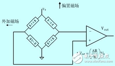
Figure 1 Schematic diagram of magnetoresistive sensor
3 system hardware design
The hardware part of the train warning information acquisition system is mainly composed of a data acquisition module and a data processing module. The data acquisition module is responsible for the collection of magnetic field signals, and its main core is a magnetoresistive sensor. When the train approaches the magnetoresistive sensor, the sensor converts the acquired magnetic field change signal into a discrete digital signal through signal amplification and a/d conversion, and transmits it to the microcontroller ( microcontroller ). The main component of the data processing module is the microcontroller . The MCU is responsible for the timing control of each chip. At the same time, in order to improve the anti-interference ability of the system, the collected data needs to be filtered, and then sent to the serial port for reading by the communication device. The hardware design block diagram of this system is shown as in Fig. 2.
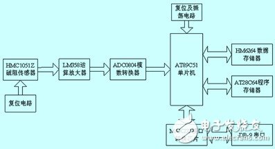
Figure 2 system hardware design block diagram
3.1 Data Acquisition Module
In this system, the magnetoresistive sensor selects the hmc1051z single-axis magnetoresistive sensor produced by Honeywell. The hmc1051z has a wide angular range with a resolution of 0.07° at ±45° with a sensitivity of 1.0 mv/v/gauss and a full-scale output of 120 mv on a 5 volt supply. No internal moving parts, low inherent impedance, strong immunity to electromagnetic noise and interference, and built-in set/reset strap to reduce temperature drift, nonlinearity, and effects on the output signal in high magnetic field environments. The on-chip bias circuit eliminates the effects of magnetic field distortion [3].
The lm358 op amp with two 4.99kΩ, two 1.00mΩ resistors and a 150pf capacitor can form an amplifying circuit with a low-pass filter with a gain of 200 and a bandwidth of about 1khz for amplification of the sensor output signal and hardware. Filtering.
The a/d converter uses an adc 0804 analog- to- digital converter with a resolution of 8 bits to perform analog-to-digital conversion on the amplified signal.
3.2 Data Processing Module
Atmel 's at89c51 microcontroller is compatible with the mcs-51's instruction system and pins, and comes with a 4kb e2rom. However, for the future upgrade and function expansion needs, the memory of at89c51 is extended here. The program memory at28c64 and the data memory hm6264lp-70 are both 8 kb in capacity, providing 13-bit addresses with p0.0 to p0.7 and p2.0 to p2.4, and 74ls373 latching their lower 8-bit addresses. These two memories are line selected using p2.5 and p2.6.
Since the signal needs to be sent to the db-9 serial port connector, max232 is used to convert between ttl and rs -232 levels. Connect the t1in pin of max232 to the serial transmit pin txd of at89c51, r1out to the serial receive pin rxd of at89c51; the corresponding rxin and t1out are connected to the rxd of the 9-pin serial port connector (db-9). Pin) and txd (pin 3).
4 system software design
The software design part of the system is mainly designed for a/d conversion subroutine and data processing subroutine, and developed with keil μvision2 development tool.
4.1 a/d conversion subroutine
The a/d conversion subroutine flow chart is shown in Figure 3. Firstly, (this design is grounded) is low, start adc0804, query interrupt 0, 100μs analog-to-digital conversion is completed after the rising edge, and the result is stored in the data latch, when the data is low The signal is sent to port p1.
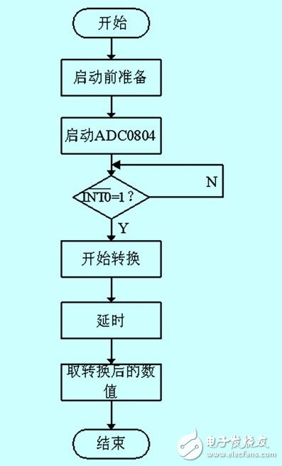
Figure 3 a / d conversion subroutine flow chart
4.2 Data Processing Subroutines
The data processing subroutine of the system performs anti-interference processing on the collected data to improve the stability and reliability of the system. The flow chart is shown in Figure 4.
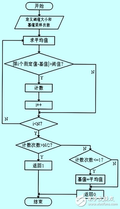
Figure 4 data processing subroutine flow chart
The data processing subroutine uses a constant threshold combined with a dynamic base value algorithm to achieve the anti-interference ability of the system, that is, the most recent acquisition data is subtracted from the base value, and the subtracted value is judged. When the value is greater than the threshold, the record is recorded. At a certain number of times, it can be assumed that the train has arrived at this time; the size of the base value can be updated in real time according to the change of the surrounding magnetic field. The program written according to this algorithm can achieve the purpose of system adaptation on the one hand, and can also freely set (threshold size and base value sampling times) anti-interference processing level to facilitate different kinds of needs.
5 Conclusion
With the magnet and the radio as the target objects, observe and record the voltage rms value of the differential output end of the magnetoresistive sensor and the voltage value after the lm358 op amp is amplified 200 times under the operating conditions away from and close to the system. The two sets of experiments were performed ten times, and the angle and position of each target object from the distance to the system was different. The experimental results are shown in Tables 1 and 2.
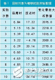
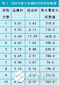
From the experimental results, the magnetic field strength of the object and the difference of the object relative to the sensor position will cause a large change in the measured value, and the change of the object with large magnetic field intensity is obvious, and the characteristic can be used to judge the arrival of the train.
6 Conclusion
This paper expounds the development process of train track alarm information acquisition system based on magnetoresistance effect from the perspective of engineering application. The system has the advantages of low power consumption, low cost and stable performance. The system can be connected with wireless devices such as gprs to form a remote alarm system, so it has certain practical value.
Bs 5896 PC Wire,Steel Strand Wire,PC Strand Prestressed Wire,Prestressed PC Steel Strand
Shandong Xindadi Holding Group Co., Ltd , https://www.xindadipcwire.com