Introduction
The modern living pattern makes the safety of family life particularly important. At present, the safety prevention and alarm system is an important guarantee for ensuring the safety of houses and residents. The best way to prevent theft is to issue a voice warning when the criminals have an intrusion attempt, increase their psychological pressure and let them leave. This system is based on this idea, using Atmel's AT89S51 microcontroller as the control core, the US ISD company's ISD1420 as a voice chip of a new family voice alarm system.
How the system works
The working principle block diagram of this system is shown in Figure 1. Irregular molecules cause changes in infrared radiation as they move within the protected area. When the infrared radiation radiated by the Fresnel lens is focused on the detecting element of the pyroelectric infrared sensor PIS-209S, the pyroelectric infrared sensor outputs a voltage signal, which is then amplified by the signal amplifying circuit and sent to the signal acquisition and The processing circuit outputs a high level to the single chip after processing.
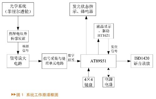
Since the criminals generally have a relatively long time outside the door, the user can combine the flow of people around his family and set the optimal alarm response time through the keyboard to distinguish them. After the setting is completed, the MCU will identify the digital signal passing through the signal acquisition and processing circuit according to the alarm response time to determine whether to start the alarm. If the alarm is activated, a voice warning is issued to the criminal by controlling the voice chip that has the alarm content, and then the voice alarm content is repeatedly played to alert the owner or the surrounding person, and then the scene is recorded to record the alarm time. At the same time, the alarm time can be queried through the corresponding button on the keyboard, and the alarm time will be displayed on the LCD screen.
Introduction to each part of the system block diagram
Pyroelectric infrared sensing device
Since the human body has a constant body temperature of about 37 ° C, infrared rays having a wavelength of about 10 μm are emitted. The pyroelectric infrared sensor PIS-209S works by detecting infrared rays of about 10 μm emitted by the human body. Pyroelectric infrared sensors are a new type of sensitive component. The high-heat material for manufacturing the pyroelectric infrared sensor is a broad-spectrum material with a detection wavelength range of 0.2 to 20 μm. In order to have a high sensitivity to infrared radiation in a certain wavelength range, the sensor is installed on the window. An interference filter. This filter only allows infrared light of certain wavelength ranges to pass, preventing light, sunlight and other infrared light from passing through. In actual use, a Fresnel lens must be installed in front of the pyroelectric infrared human body sensor. The Fresnel lens is a specially designed optical lens made of plastic that focuses the infrared radiation radiated by the human body onto the pyroelectric infrared sensor, thereby increasing the sensitivity of the sensor and expanding the monitoring range. It can produce alternating high-sensitivity areas and dead zones of infrared radiation to accommodate the changing characteristics of the pyroelectric detection elements. The two reverse series pyroelectric elements of the sensor are exposed to moving objects, so the infrared radiation of the human body constantly changes the temperature of the pyroelectric element in the form of infrared pulses, so that it outputs a series of pulse signals, if the human body is in front of the sensor If you don't move, there will be no output.
Signal amplifier circuit
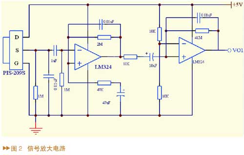
The signal amplification circuit is shown in Figure 2. The pyroelectric infrared sensor PIS-209S will output a voltage signal, and then the signal will first pass through a bandpass filter composed of a resistor capacitor. The upper limit cutoff frequency of the filter is 16 Hz, and the lower cutoff frequency is 0.16 Hz. The detection signal voltage output by the electric infrared sensor is very weak (usually only about 1mV), and it is a changing signal, and the effect of the Fresnel lens makes the output signal voltage pulsed (the frequency of the pulse voltage is determined by the measured object). The moving speed is determined to be about 0.1 to 10 Hz, so the voltage signal output from the pyroelectric infrared sensor should be amplified. After two stages of general-purpose integrated operational amplifier LM324 amplification, sufficient gain is obtained, and the VO1 signal is output to the signal acquisition and processing unit circuit.
Signal acquisition and processing unit circuit
The hardware circuit is shown in Figure 3. The signal VO1 transmitted by the signal amplifier is preamplified by the operational amplifier OP1 in the infrared sensing signal processor BISS0001, and then capacitively coupled to the operational amplifier OP2 for secondary amplification, and then bidirectionally amplitude-modulated by the voltage comparators COP1 and COP2. After processing, the valid trigger signal is detected to start the delay time timer. The output signal is connected to the single chip through the transistor VT1, and the output signal VO2 is for reading.

BISS0001 is a CMOS digital-analog hybrid ASIC composed of an operational amplifier, a voltage comparator and a state controller, a delay time timer, a blocking time timer, and a reference voltage source. It is widely used in a variety of sensors and delay controllers, with independent high input impedance operational amplifiers, can be matched with a variety of sensors for signal preprocessing. Its internal bidirectional discriminator can effectively suppress interference, and has a built-in time timer and a lockout time timer. The structure is novel, stable and reliable, and the adjustment range is wide. It has two working modes: repeatable triggering and non-repeatable triggering. Pin A of this circuit is connected to the power supply, so that the circuit is in the repeated trigger mode. In the timing period TX, the output of BISS0001 is high, the transistor VT1 is saturated and the collector is low, and this signal is sent to the microcontroller; at the end of Tx, BISS0001 enters the blocking period Ti, and its output becomes Low level, the transistor is turned off and its collector is high. The TX timing interval can be determined by the resistors and capacitors connected to pins 3 and 4 of BISS0001.
Voice recording and reproducing circuit
The system's voice recording and playback circuit is shown in Figure 4. The AT89S51 is used as the CPU in the circuit, and its P0.0~P0.5 is connected to the ISD1420. When designing the circuit, all the address terminals and control terminals of the ISD1420 must be connected to the high level or the low level reliably and cannot be left floating. Otherwise, the playback may stop. The microphone signal coupling capacitor is the same as the capacitor connecting the MICREF terminal to the analog ground. It is important to note that the SP+ and SP- terminals of the ISD1420 chip must not be directly grounded. They can only be connected to the speaker or left floating. When the external power amplifier is connected, the single-ended output is used, and the other end is connected to 10μF to ground or suspended, otherwise the ISD device may be damaged.

The AT89S51 microcontroller is a low-power, high-performance CMOS 8-bit microcontroller with 4KB of online programmable (ISP) flash-ready program memory that can be erased and erased 1000 times. ISD1420 chip has low power consumption (0.5W) during standby, 15mA playback current; 20s playback time, expandable cascade; sustainable playback, can also be recorded in sections, minimum segment: 20s/160 segments = 0.125s, Can be segmented into 160 segments; recording and releasing times up to 100,000 times; power-off information storage, no backup battery, information can be stored for 100 years; no special programmer and voice developer required; high-priority recording, low level or Negative edge playback. Its pin SP+, SP- is the audio signal output terminal, which can drive 8~16Ω speaker; MIC is the microphone input terminal, can be used with electret microphone, through capacitive coupling; MICREF is the microphone input reference terminal, if it should not be left floating.
Usually, the driving capability of the ISD1420 is limited (0.5W), and the effect is not ideal when directly connected to the speaker. If the speaker is connected to more than 1W, distortion will occur. Generally, speakers below 1W can be driven by chips such as LM386, D2283, D2822, MC34119, and TA7368. This circuit selects the speaker below 1W, and uses the low voltage universal integrated power amplifier LM386 as the driver chip of the speaker. The circuit is shown in Figure 5. 1W~10W speakers are driven by TDA2003 and LA4440 chips. The circuit using TDA2003 as the speaker driver chip is shown in Figure 6.

Keyboard and display circuit
The keyboard adopts 4×4 determinant; the display adopts HT1621 liquid crystal display driver chip, which is a multi-function LCD driver with 32×4 memory, only 4 interfaces are connected to the controller and can provide watchdog clock. In addition to the 4-digit number, the LCD screen has up to 16 Chinese characters such as alarm, fire alarm, unprepared, bypass, and arming to form an intuitive Chinese character display. The monitoring point number, time, and fortification flag are displayed when the fortification point is set, and the date, time, and accident point are displayed when the accident alarm record is queried. At the same time, the watchdog clock provided by the HT1621 liquid crystal display driver chip is used to realize automatic reset when the keyboard system crashes, so that the keyboard system resumes work.
The power supply of this system consists of two parts: mains and spare battery. Under normal conditions, the mains supply provides DC power to the alarm system through rectification, filtering, and voltage regulation, and automatically charges the battery. When the utility power fails, the battery is automatically put into use to ensure that the alarm system can work normally, and at the same time, the power failure warning information is sent to the outside world.
System software design
The basic task of software design is to realize the programmable function of the user security function, and monitor the alarm in real time for the security zone. This software design uses a structured programming approach. The main work in the software design is to complete the processing of the digital signal VO2 output by the single-chip microcomputer to the infrared sensor signal processor BISS0001, the software implementation of the voice service and the timely voice recording and playback. The block diagram of the software design flow is shown in Figure 7.

The BISS0001 chip has been subjected to anti-interference processing on the signal transmitted from the sensor, and the signal VO2 is obtained. In order to improve the reliability of the system detection, the VO2 is further processed by the single chip microcomputer. When the voice chip 1420 is programmed, it is written according to its working process. Press and hold the “REC†button while recording, the indicator light will be on, and the microphone on the board will be recorded. When the button is released, the recording will stop and form a segment. Press the “PE†button during playback to play all the recordings, and stop the playback automatically after one end. Press and hold the “PL†button to play the sound, and the loose button will stop. The address line of the ISD1420 has 8 bits, and 6 bits are connected to the I/O port of the AT89S51. The minimum voice length is 125ms. Each voice can be controlled by the address line. Each 125ms is an address, which is controlled by six address lines A2~A7. After each segment of the recorded voice of the user, the chip automatically sets an end-of-segment flag (EOM). After the chip is full, an overflow flag (OVF) is set. The MCU control circuit performs the playback operation according to the starting address of a certain segment, and the end of the segment is encountered. The flag (EOM) automatically stops the playback, and the MCU receives the segment end flag (EOM) to start triggering the start address of the next segment of speech. With such control, it is possible to combine the voices of many different segments into one sentence for playback, and realize automatic combination of voices.
Conclusion
The system realizes the home voice alarm function. After many tests, the system works stably. The user can personally set different modes such as going out and do not disturb through the keyboard to realize the voice service function. The alarm system has the advantages of simple structure, low cost and novelty, and is suitable for home use.
Stair Railing,Balcony Railing,Aluminum Extension Ladder Railing
Steel Grating,Miscellaneous Co., Ltd. , http://www.steel-grating-manufacturer.com