HC Security Network News Liquefied petroleum gas, gas and other combustible gas as fuel often cause leakage and cause poisoning and fire accidents. There are many types of existing flammable gas leak alarms, which are mainly used in industrial factories and mines. They are bulky and have high prices and are difficult to generalize to households. Although there are also some simple alarms, they are also complicated in structure and high in price. It is more difficult to promote them to homes. For this reason, the problem of high device cost has been solved by a combination of simple digital and analog integrated circuits. A compact combustible gas leak alarm has been developed. It has a simple structure and low cost (the cost of the main circuit component is only about RMB 3, and the total material cost for the case and power supply is only ten yuan). The alarm sensitivity is within the performance range of the sensor. Randomly adjustable. The trial results show that the device is easy to use and the effect is very good. The control function can be increased by simply improving the device, and the device such as the fan can be automatically controlled and turned on. The flammable gas leak alarm is not only suitable for home, but also for industrial and mining enterprises, and its alarm sensitivity, alarm reminding function, reliability, etc. is better than the existing products.
1 System Design Optimization Comparison
Currently, the flammable gas leakage alarms are divided into two major categories. One is a smart alarm with a single-chip microcomputer as the core, including signal conditioning, A/D sampling, and input/output circuits. These are relatively complex. The other type is implemented entirely in hardware and the circuit is very complicated. Both of these technologies use more complex circuits to solve the initial alarm problem of combustible sensors. The reason for the initial alarm is that the conductivity of the sensor has not yet reached the steady state value at the beginning of power-on, which leads to false alarm. After about 3 minutes, the sensor's conductivity reaches a steady value and the alarm stops. In order to solve the initial alarm problem, the following two options can be used: 1) A secondary alarm scheme is adopted, which uses the equivalent flammable gas concentration of the initial conductivity of the sensor as the first-stage alarm concentration. Only the warning lamp is lit at this stage. The horn does not ring. The second phase of the alarm is to turn on the sound alarm when the flammable gas leak concentration reaches a critical dangerous concentration. Such a scheme requires a relatively complicated two-stage comparison alarm circuit, which is not strong and unreliable, and the alarm sensitivity is not adjustable. 2) The alarm scheme of comparison or feedback delay is adopted, but the circuit is very complicated and the cost is high. Therefore, using hardware design to reduce costs is the key. Here, a design scheme using digital and analog integrated circuits is proposed to solve the alarm and secondary alarm problems and achieve good results.
2 Device Selection and Operation
There are many kinds of gas sensors and their performance varies. Here choose MQ-KC type sensor, it is a kind of new type of resistance type gas sensitive type element, can be used for natural gas, coal gas, petroleum gas leak detection. With high sensitivity, long-term stability, long life, low price, low power consumption, can easily use the battery and so on. MQ-KC type sensor principle: The sensor is connected to the specified load. In the initial stage of power-on, the conductivity of the sensor exhibits a higher value, and reaches a steady state value in about 3 minutes. If it is placed in a combustible gas with a certain concentration, its conductivity will increase. Within a certain range, the higher the concentration of combustible gas, the higher the conductivity of the sensor, if the sensor and the load in series, the load will cause the voltage change , Read this change voltage, through comparison, amplification can achieve alarm and control functions.
3 Hardware Circuit Design
3.1 Basic alarm circuit
The MQ-KC sensor is rated at 9 V and requires a load resistor. If the signal extraction and comparison circuit is designed with discrete components, the number of components is high, the cost is high, and the effect is not good. For this purpose, a single-supply 9 V supply is used and an integrated dual op amp with a certain drive capability is implemented.
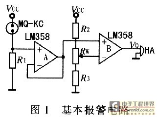
Figure 1 basic alarm circuit In Figure l, R1 is the load resistance required by the sensor, the resistance is 120 Ω, Vcc is 9 V power supply voltage; A, B is LM358 dual op amp, A is a follower, play a buffer isolation role, in order to The voltage VR1 on R1 is substantially all applied to the non-inverting input of comparator B. RW is the alarm sensitivity adjustment potentiometer. In the steady state, adjust RW such that the voltage V- applied to the inverting input of the comparator is slightly higher than the voltage VR1 on R1 in the steady state. The higher the voltage, the lower the alarm sensitivity. After power-on and the sensor reaches steady state, MQ-KC is a relatively stable fixed resistance. When Vcc is not changed, VR1 is basically a fixed value and remains unchanged. When flammable gas leaks, the sensor comes into contact with flammable gas, causing its conductivity to rise and the resistance to drop, causing VR1 to rise. When VR1 is higher than V-, the comparator outputs a voltage greater than 7 V, making the buzzer HA issued drop, drop alarm sound. If you use this voltage to control a relay, you can achieve the control function. In order to improve the anti-interference ability, a filter capacitor can be connected in parallel at the V-end of R1 and B.
The values ​​of R1, R2, and RW should not be too small to reduce the power supply current. Its value can be estimated by equation (1). In the estimation, RW may not be considered temporarily.

formula
Let V- = VR1, take R3 = 2 kΩ, know Vcc = 9 V, you can find R2. The device R2 = 10 kΩ, RW = lO kΩ.
3.2 Initial alarm circuit
The insufficiency of the basic alarm circuit shown in FIG. 1: When the power is turned on at the beginning, the sensor has not yet reached the steady state, its resistance value is smaller, and VR1 is larger, causing the buzzer HA to alarm. In order to solve this problem, a digital signal controlled analog switch is used, and the control signal adopts a simple capacitor charging delay circuit, and the schematic diagram is shown in FIG. 2 . The output V0 of the comparator B in FIG. 1 is added to the input of the analog switch 4066, and the output of the switch is connected to the buzzer HA. On initial power-up, voltage VC on capacitor C is 0,4066 is non-conducting and HA will not alarm no matter how high the value of V0 is. With the charging of the capacitor, the VC keeps rising. When the control threshold of 4066 is reached, the 4066 is turned on, which means that it can enter the alarm state. Capacitors charge their voltage to the control threshold threshold of 4066, which is the delay time. The value of capacitor C and resistor R can be determined according to the delay requirement. For reliability, take RC = 1/2T, T is the initial settling time of the sensor. The device takes R = 1 MΩ, C = 100μF, which can achieve a reliable delay.
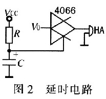
Delay circuit
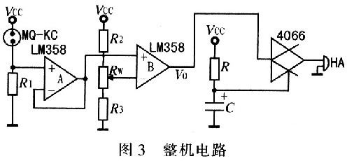
Whole circuit
3.3 hardware circuit design and debugging
Combining the above two circuits constitutes a complete circuit, as shown in FIG. In order to make V-stability constant, R1, R2 should use precision metal film resistors. After the device is warmed up for 3 minutes, measure the voltage VR1 on R1 with a multimeter and measure it as 1.7 V. If you want the alarm concentration of the device to be x%, if conditions permit, the sensor can be placed in a combustible gas with a concentration of x% (monitored with a gas analyzer), and after 10 s the voltage on R1 is measured to obtain VR1. Adjust RW to adjust V- to slightly less than VR1. In normal use, when the flammable gas leakage concentration reaches the calibration concentration x%, the device will alarm. If the control device is added, the fan may be turned on or the valve may be closed. When there is no condition, adjust RW and adjust V- to slightly larger than VE1 to ensure no alarm in normal air environment. Then the device is placed next to the gas cooker, the cooker switch is turned on, the flame is blown out, a small amount of flammable gas leaks out, and the device should be alarmed. To increase the alarm concentration, the adjustable RW increases V-, whereas it should decrease V-.
3.4 Power Design
The device's total supply current is less than 20 mA, so a 9 V battery can be used. The prototype uses an AC 220 V supply and is regulated using a 7809 three-terminal regulator.
4 trial experiment and results
4.1 Trial results
Place the device in the kitchen, warm it up for 3 minutes, and the device has no initial alarm. Close the kitchen door and let out the proper amount of gas. After a few seconds, the device starts to alarm and then the device is removed from the site. The alarm stops after about 30 seconds. In the normal air kitchen, the device is warmed up for 3 minutes and then placed on the side of the gas stove. The cooker switch is turned on and the flame is extinguished. After a few seconds the device starts to alarm. When gas is still in the kitchen, it will continue to alarm. , Put it out the window, it can recover faster and stop the alarm.
4.2 Application and Installation
This device can not only be used for industrial gas leakage alarm, but because of its low cost, it can also be extended to ordinary families, as a gas shower device and kitchen gas leak alarm. As long as it is installed near the gas device (the best effect within 1 m), an automatic leak alarm can be realized. When installing, care should be taken not to place the unit at the vent.
5 Concluding remarks
The device uses a digitally controlled integrated analog switch and resistance-capacity charging circuit to solve the initial false alarm problem of flammable gas alarm devices. A dual-integrated operational amplifier powered by a single power supply is used for signal extraction, comparison and alarm driving, and the device The alarm sensitivity can be arbitrarily adjustable within the sensor performance range. To achieve the following performance: power consumption less than 0.3W; sensitivity V1/V0> 2; response time is less than lO s: recovery time is less than 30 s. The flammable gas alarm device adopts a combination of digital and analog integrated circuits, which greatly reduces the number of components, thereby improving the stability and reliability of the device, and making the cost of the main circuit components less than 3 yuan. To make it have a higher cost performance, but also according to user needs and specific circumstances to further improve the alarm device. Add a level control circuit, as long as the output of the comparator B plus a level relay drive can be achieved.